SDI 2227 Q-LITE TACTICAL-GRADE INERTIAL MEMS DC ACCELEROMETER MODULE
With a wide thermal range, high precision, and low mass, the SDI 2227 is a tactical-grade module built for consistent, low-noise inertial performance.
Meet the SDI Model 2227: Tactical Accuracy with Industrial Durability
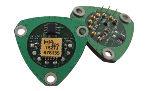
The SDI Model 2227 is a low-mass, low-power module designed for tactical-grade inertial and tilt applications. At its core is SDI’s high-performance Model 1527 accelerometer, known for tight bias repeatability, low noise, and long-term stability.
Engineered to replace quartz-based accelerometers without sacrificing performance, the 2227 is ideal for navigation, aerospace, defense, and advanced robotics applications requiring higher thermal tolerance and stable output.
Key Features And Use Cases
- Excellent Long-Term In-Run Bias Stability
- Small Bias and SF Temperature Coefficients
- Calibrated Internal Temperature Sensor
- ±4.0 mA Full Scale Current Output
- ±9 to ±16 Volt DC, 16 mA Maximum
- -55 to +125°C Operation
- Two Built-In Self Tests
- Durable to 5000+g Mechanical Shocks
- Hermetically Sealed MEMS Accelerometer
- Serialized for Traceability & RoHS Compliant
- Low Mass: 5.6 grams
- Inertial
- Navigation
- Instrumentation
- OEM Integration
- Robotics
- Aerospace
PERFORMANCE BY G-RANGE
| PERFORMANCE | ±10G | ±25G | ±50G | UNITS |
|---|---|---|---|---|
| Bias, Typical | ±0.2 | ±0.2 | ±0.2 | % of FS |
| Bias Long-Term Repeatability (1σ) | 1.00 | 1.50 | 3.0 | mg |
| Bias Temperature Coefficient, Typical | 5 | 5 | 5 | PPM/°C of FS |
| In Run Bias Stability at +1g, 2-40,000 sec. (AV Min) Typical | 12 | 30 | 60 | μg |
| Scale Factor Sensitivity, Nominal, +/- 0.5% | 400 | 160 | 80 | uA/g |
| Scale Factor Long Term Repeatability (1σ) | 300 | 300 | 300 | PPM |
| Scale Factor Temperature Coefficient, Typical | 12 | 10 | 10 | PPM/°C |
| Input Axis Misalignment, Typical | 5 | 5 | 5 | mrad |
| Vibration Rectification, Typical:10-50 Hz, Random | 20 | 35 | 50 | μg/g2 rms |
| Vibration Rectification, Typical:50-200 Hz, Random | 50 | 100 | 150 | μg/g2 rms |
| Output White Noise, Typical | 18 | 25 | 50 | μg/√Hz rms |
| Velocity Random Walk, Typical | 0.007 | 0.012 | 0.025 | m/s√Hr |
| RMS Model Residual (+/- 1g), Typical | 15 | 12 | 12 | PPM of FS |
| Frequency Response, DC to -3 dB, Nominal | 0 – 600 | 0 – 900 | 0 – 1400 | Hz |
Need Help Choosing the Right Accelerometer?
Performance and Packaging
The 2227 is built on a high-temperature PCB with a compact, low-mass design (5.6 grams). It integrates a MEMS accelerometer with temperature sensing and current output circuitry into a package optimized for high-precision, small-footprint installations.
Package Dimensions

PERFORMANCE – ALL MODELS
Scale = measured value; FS = Full Scale = absolute output = 4000 mV
| PARAMETER | MIN | TYP | MAX | UNITS |
|---|---|---|---|---|
| Temperature Sensor Sensitivity, Nominal +/- 0.3°C | 1 | uA/°C | ||
| Temperature Sensor Calibration Error | 0.5 | °C | ||
| Accelerometer Non-Linearity | 0.1 | 0.2 | % of FS | |
| Turn-On Time to < 150 ppm of Output Value | 0.5 | mSec | ||
| Operating Voltage for Full Scale Acceleration Input | +/-9 | +/-9 | Volts | |
| Quiescent Operating Current at +/-12 Volts | 10 | 12 | mA | |
| Operating Temperature | -55 | 125 | °C | |
| Storage Temperature | -55 | 125 | °C | |
| Applied Voltage on Digital Self-Test Pins 2 and 7 | -0.5 | 5.5 | Volts | |
| Peak Continuous Vibration (Operating and Non-operating) | 200 | % FS | ||
| Mechanical Shock (0.1 ms) | 5000 | g - peak | ||
| Mass | 5.6 | grams | ||
| PCB Material: Rigid Polyimide, CTE | 16 | ppm/°C |
NOTICE: Stresses greater than those listed may cause permanent damage to the device. These are maximum stress ratings only. Functional operation of the device at or above these conditions is not implied.
Operational Highlights
The model 2227 input axis is perpendicular to the PCB. The seismic center is located at the center of the PCB inside the LCC accelerometer, approximately 0.110 inches (2.75 mm) above the top of the PCB, the reference surface for the 2227.
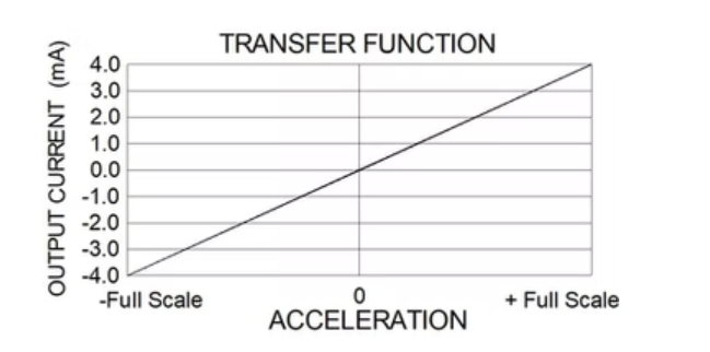
The Model 2227 generates an output current, the value of which varies with acceleration as shown in the adjacent figure.
Sales and Support
Reliable Customer Support from Start to Finish
Get a Quote
Our sales team is available to assist with pricing, lead times, and customized solutions tailored to your specific needs. We work closely with you to ensure you get the best accelerometer solution for your application.
Order Now
With a streamlined ordering process and secure procurement options, placing an order with SDI is simple and efficient. Our commitment to fast processing ensures minimal downtime for your projects.
Tech Support
From initial setup to ongoing performance optimization, our technical support team provides expert guidance to ensure proper integration and reliable sensor operation.
Our Distributors
Our experienced U.S. sales representatives provide direct assistance for domestic customers, ensuring a smooth procurement process with personalized service. International customers can rely on our global distributor network for localized support, timely deliveries, and expert guidance in their regions.
Sign Up For Our Newsletter
Sign up for our newsletter to receive the latest insights on sensor technology, industry trends, and product updates. Be the first to know about advancements in MEMS accelerometers and how they can benefit your applications.