SDI 2290 HIGH-PRECISION MEMS DC REFERENCE ACCELEROMETER
The SDI Model 2290 offers stable, low-noise performance and inertial-grade accuracy, making it the ideal single-axis reference for measurement, calibration, and performance verification.
Meet the SDI Model 2290: Accuracy and Long-Term Stability in a Compact Plug-and-Play Module
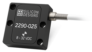
The SDI 2290 is a single-axis MEMS DC precision reference accelerometer engineered to serve as a dependable standard for calibration and highly stable measurement. It combines Silicon Designs’ tactical-grade Model 1527 MEMS chip with proprietary low-noise electronics, all housed in a rugged, anodized aluminum enclosure and wired for easy integration.
Built to provide consistent output across a wide frequency and temperature range, the 2290 simplifies calibration and instrumentation tasks while maintaining high accuracy over time. Its plug-and-play design includes a simple 4-wire, integrated 10’ cable for seamless DAQ integration.
Key Features And Use Cases
- Excellent Long-Term Stability
- Flexible +8 to +32 VDC Power
- ±4V Differential Output
- -55 to +125°C Operating Temperature Range
- Responds to Frequencies from Zero (DC) up to 1800 Hz
- Integrated 10’ Cable with Simple 4-Wire Connection
- Rugged Anodized Aluminum Case, Module Mass: 9 Grams
- Fully Calibrated and Serialized for Traceability
- Lab
- Robotics
- Seismic
- Tilt
- Vibration
- Center of Gravity
- Monitor
- Instrumentation
Need Help Choosing the Right Accelerometer?
Performance and Packaging
Packaged in a compact 1-inch square anodized aluminum housing, the 2290 includes a factory-calibrated MEMS sensor, built-in temperature compensation, and integrated wiring. It is REACH and RoHS compliant, ECCN 7A994 classified, and does not require ITAR controls.
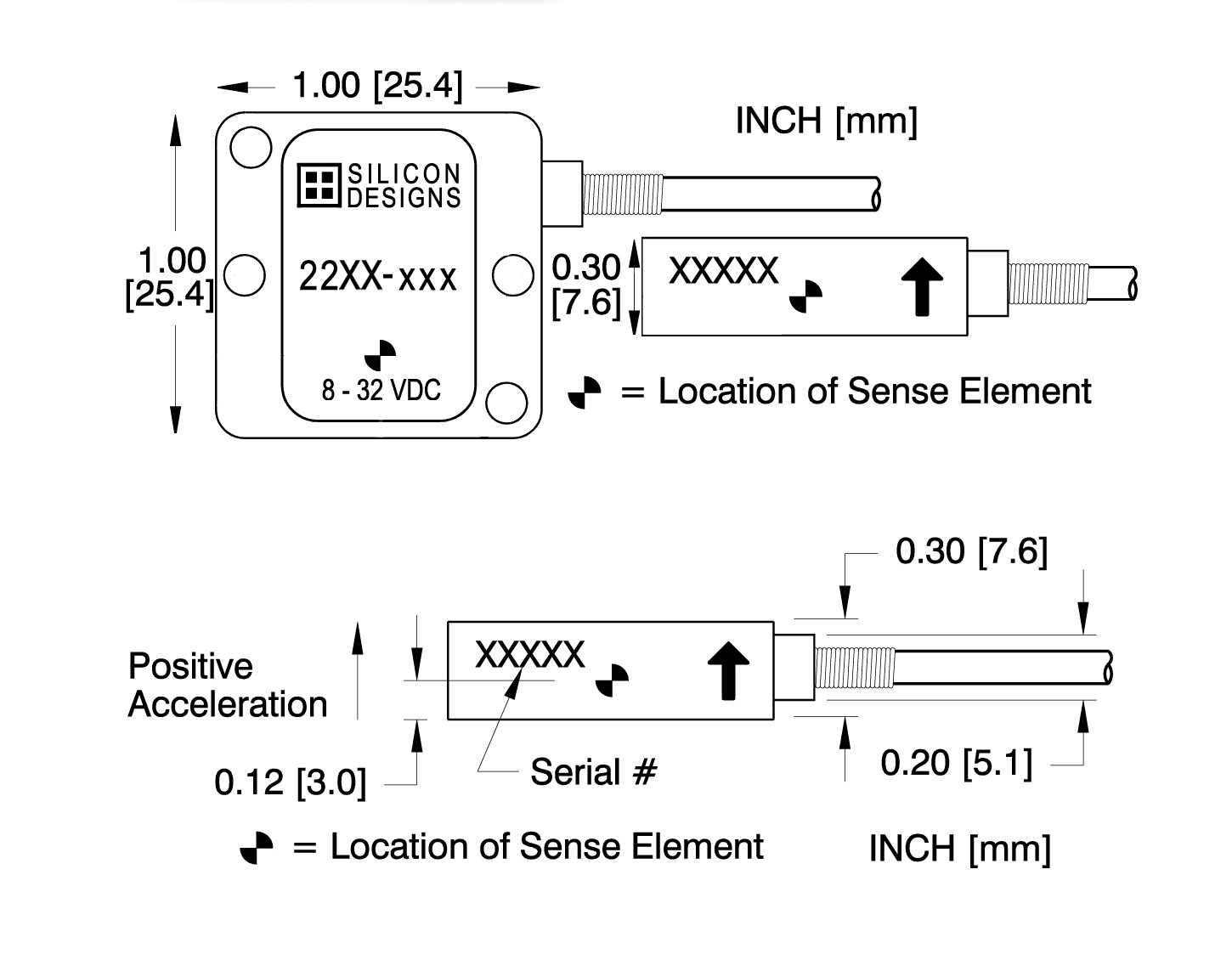
Package Dimensions
Performance – All Versions
All Models: Unless otherwise specified, Vs=+8 to +32 VDC, TC=25°C, Differential Mode. Span=±g range = 8000 mV
| PARAMETER | MIN | TYP | MAX | UNITS |
|---|---|---|---|---|
| Bias Calibration Error (%) | 0.25 | 0.6 | + % of span | |
| Bias Calibration Error (mV) | 20 | 48 | ± mV | |
| Scale Factor Calibration Error | 0.5 | 1.25 | ±% | |
| Non-Linearity (-90 to +90% of span) | 0.15 | 0.5 | +% of span | |
| Bias Temperature Shift (Coefficient) | -75 | 0 | +75 | (PPM of span)/°C |
| Scale Factor Temperature Shift (Coefficient) | -75 | 0 | +50 | PPM/°C |
| Cross Axis Sensitivity | 2 | 3 | ±% | |
| Power Supply Rejection Ratio | 50 | >65 | dB | |
| Output Impedance | 1 | Ω | ||
| Output Common Mode Voltage | 2.5 | VDC | ||
| Operating Voltage | 8 | 32 | VDC | |
| Operating Current (AOP & AON open) | 7 | 10.5 | mA DC | |
| Operating Temperature | -55 | +125 | °C | |
| Mass (excluding cable) | 9 | grams | ||
| Cable Mass (10' integrated cable) | 5 | grams/foot |
NOTICE: Stresses greater than those listed may cause permanent damage to the device. These are maximum stress ratings only. Functional operation of the device at or above these conditions is not implied.
Operational Highlights
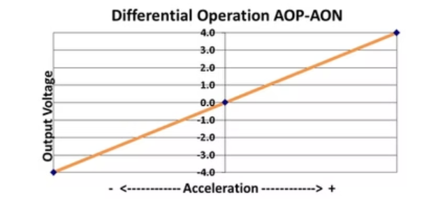
These accelerometer modules produce differential analog output voltage pairs (AON & AOP) which vary with acceleration. The signal outputs are fully differential about a common mode voltage of approximately 2.5 volts. At zero acceleration, the output differential voltage is nominally 0 volts DC; at ±full scale acceleration, the output is ±4 volts DC, respectively, as shown in the figure. The output scale factor is independent from the supply voltage of +8 to +32 volts.
Frequently Asked Questions
Why does the accelerometer read zero G's when it's in free fall?
All accelerometers are used to measure increasing or decreasing acceleration, and they can detect vibration because it is a change in acceleration between multiple directions. Free fall, by definition, is a static acceleration, which means the object may be moving, but its acceleration is not changing at all. SDI’s MEMS DC accelerometer technology allows it to measure free fall because it doesn’t require any change of acceleration to supply data, and therefore it will report back 0g of acceleration.
How do I choose the right g-range for my application?
The g-range of your accelerometer should match the maximum acceleration your system is expected to experience—but avoid going unnecessarily high. Selecting too high of a g-range can reduce measurement clarity, while too low of a range can cause the sensor to saturate if the acceleration exceeds its limit. Also consider the frequency response. Each Silicon Designs sensor has a MEMS sense element tuned to its specific g-range, which affects its frequency range and noise profile. Be sure to check the product datasheet or visit our How To Choose Your Accelerometer guide for more detailed recommendations. You can also reach out to our team for help identifying the best fit for your application.
My accelerometer appears to be broken. When I place it on the desk with the lid facing up, it reads +1G. How do I fix this?
SDI’s MEMS DC accelerometers are designed to respond to the Earth’s gravity. If you are on Earth, then you are in a +1g gravitational field. Turn the device over and you will see a -1g reading, which you can use to perform your own bias calibration of the device. Visit our Technology page to learn more about how SDI’s accelerometers work. Also see the How to Calibrate Your Accelerometer page for how to use this feature for self-calibration.
Do I need a charge amplifier or signal conditioning to use my Silicon Designs MEMS DC accelerometer module?
All Silicon Designs MEMS DC accelerometers feature integrated amplifiers, so an additional one is not required. Signal conditioning is optional.
Optional Accessories
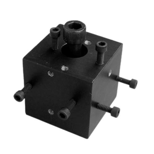
MODEL 2230 3-AXIS MOUNTING BLOCK
- INFO
- Rugged, black anodized, precision-machined 6061-T6 aluminum construction
- Block mass = 79 grams
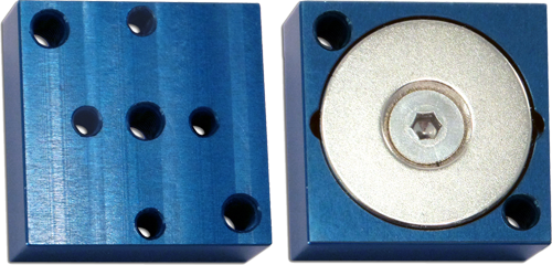
MODEL 2232 MAGNETIC MOUNTING BLOCK
- INFO
- Rugged blue anodized aluminum construction
- Block mass = 23 grams
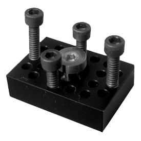
MODEL 2235 1-AXIS STUD MOUNT BLOCK
- INFO
- Rugged black anodized aluminum construction
- Block mass = 6.2 grams
+8 to +32 VDC POWER VERSIONS
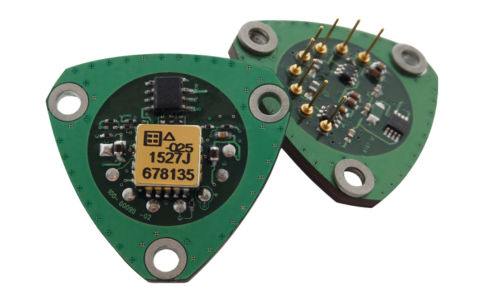
MODEL 2227 Q-MODULE
- INFO
- STATS
- APPLICATIONS
- Power: ±9 to ±16 VDC
-
Output:
- ±4.0 mA Full Scale
- Current Output
- Current: Max 16 mA
- Connection: 8-Pin Quartz Accelerometer Pin-Out
- Mass: 5.6 grams
- Package: Hi-Temp Open Printed Circuit Board
- Temperature: -55 to +125°C
-
Available:
- 10g
- 25g
- 50g
- Mechanically compatible with industry-standard quartz accelerometer fixtures and equipment
- Zero to medium frequency inertial and tilt applications
- R&D alternative for existing quartz accelerometer systems
Sales and Support
Reliable Customer Support from Start to Finish
Get a Quote
Our sales team is available to assist with pricing, lead times, and customized solutions tailored to your specific needs. We work closely with you to ensure you get the best accelerometer solution for your application.
Order Now
With a streamlined ordering process and secure procurement options, placing an order with SDI is simple and efficient. Our commitment to fast processing ensures minimal downtime for your projects.
Tech Support
From initial setup to ongoing performance optimization, our technical support team provides expert guidance to ensure proper integration and reliable sensor operation.
Our Distributors
Our experienced U.S. sales representatives provide direct assistance for domestic customers, ensuring a smooth procurement process with personalized service. International customers can rely on our global distributor network for localized support, timely deliveries, and expert guidance in their regions.
Sign Up For Our Newsletter
Sign up for our newsletter to receive the latest insights on sensor technology, industry trends, and product updates. Be the first to know about advancements in MEMS accelerometers and how they can benefit your applications.