top of page

SDI'S TECHNOLOGY

Since 1983, Silicon Designs has been an industry pioneer in the design, development and manufacture of MEMS accelerometers and chips with DC response, integral amplification, and simple analog output. The world-class MEMS DC accelerometers and chips manufactured by SDI operate much differently than industry piezoelectric and piezoresistive designs, due to their added capabilities to effectively measure both DC (i.e. static) and low-frequency vibration and acceleration; their relative indifference to temperature changes; and their exceptionally low noise. Read on to learn the what’s, how’s, and why’s of Silicon Designs MEMS capacitive accelerometer technology.

The Short Answers

WHAT IS A MEMS VARIABLE CAPACITANCE ACCELEROMETER?

​

The term "MEMS" stands for Micro Electro Mechanical System, which is a miniature machine that has both mechanical and electronic components.  Each Silicon Designs industrial- and inertial-grade MEMS DC accelerometer chip consists of a sense element (i.e., the MEMS) and an electronics chip called an “ASIC”, which stands for Application Specific Integrated Circuit.

​

SDI’s accelerometers use capacitance change, also referred to as the variable capacitance, caused by acceleration force as the sensed parameter.  This is done by measuring the space (i.e. the capacitance) between the “wings” of a sense element and the sensor plates below them.  The information is processed by the ASIC (Application Specific Integrated Circuit), which converts the small capacitance changes of the sense element into a useful electrical signal.   

​

The sense element, which is designed and manufactured in-house, and the ASIC are attached to a 20-pin, gold and ceramic package using standard die attach and wire bonding techniques, and the package is then solder sealed to provide a simple, strong, fully hermetic device. 

​

SDI accelerometer internal MEMS
SDI inertial accelerometers 1525 1527
SDI industrial accelerometers 1521 1522 1531

HOW DOES IT WORK?

​

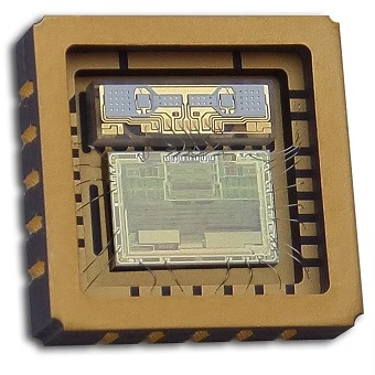
Interior of SDI Model 1410

SDI Model 1410L and 1410J digital accelerometers

Since its earliest days, Silicon Designs has been a pioneer in the development of innovative capacitive-style MEMS DC accelerometer designs, by combining two moving upper plates (the “wings”) in a mirror image configuration. This has two benefits:

  1. It eliminates the acceleration dependent cross axis sensitivity.  In a standard pendulous (single wing) accelerometer, as the proof mass rotates out of plane, it becomes sensitive to accelerations in the cross axis.

  2. Common mode asymmetries can be eliminated by the sensor's on-board electronics.

​​

SDI MEMS sense element drawing

Each wing has a small, inner half and a wide, outer half, resulting in a center of mass that is offset from the axis of rotation.  In roughly the middle, the wing is attached to a pedestal by two X-shaped torsion bars.  The pedestal suspends each entire wing directly above two fixed, conductive, capacitor surface plates, forming a fully active capacitance bridge.  The combination of the mechanical wings and the electrical capacitor plates form the MEMS portion of the accelerometer.

​

When the wing shifts each side up or down, much like a teeter-totter, about the torsion bar axis, the average distance between the wing and one surface plate decreases, increasing the capacitance for that plate, while simultaneously increasing the distance to the other plate, decreasing its capacitance.  The sense element circuitry then communicates these changes to the ASIC. 

​

SDI accelerometer MEMS Sense Element

The ASIC functions as a capacitance-to-voltage converter. It utilizes a switched-capacitor amplifier to convert the microscopic movements of the sense element wings into a voltage output, which is linearly proportional to the applied acceleration. The differential voltage output spans from -4V for negative full-scale acceleration to +4V for positive full-scale acceleration.

​

WHY USE A SILICON DESIGNS MEMS DC ACCELEROMETER?

​

A MEMS DC accelerometer provides several benefits when compared to the piezoelectric and piezoresistive technologies used in many of today’s accelerometers.

​

There is no lower frequency limit to the sensor’s measurement range.  Piezoelectric type accelerometers require a dynamic input of some minimum frequency to generate a response, and below this threshold the signal deteriorates.  SDI’s variable capacitance sensing technology allows for response to DC accelerations as well as dynamic vibration.  Because it is powered, the sensor doesn’t require any movement to provide a useful signal – it will always report back with the capacitance between those wings and the plates below, even when there’s no movement at all. 

​

The MEMS capacitive sense element is relatively insensitive to temperature.  Although spacing can change with temperature due to thermal expansion, the low thermal coefficient of expansion of many materials can produce a thermal coefficient of capacitance about two orders of magnitude less than the thermal coefficient of resistivity of doped silicon.  Moreover, the differential design of SDI's accelerometers ensures that errors due to thermal expansion are cancelled.  Capacitance sensing therefore has the potential to provide a wider temperature range of operation, without requiring additional compensation, as compared to piezoresistive sensing. 

​

Unique MEMS capacitive sense elements for every G-range mean drastically reduced noise.  SDI designs and fabricates its own MEMS sense elements, and the geometry of each G-level is customized to create the optimal combination of damping, flexibility, and sensitivity.  For example, the wings of a 2G sense element must move much slower than those of a 200G sense element.  By optimizing sense element designs to reduce adjustments of the ASIC’s gain during programming, SDI is able to manufacture some of the lowest noise accelerometers in the industry.

​

The Science (The Long Answers)

SDI'S CUSTOM MICRO-MACHINED SENSE ELEMENT (MEMS)

​

Each MEMS sense element manufactured by SDI consists of a plate of single crystal silicon that is free to rotate about a torsional axis.  Each side of the plate form capacitors with electrodes on the fixed substrate. The structure is asymmetrically shaped so that one side is heavier than the other, resulting in a center of mass that is offset from the axis of rotation. 

​

On the substrate surface, beneath the sense element wing, two conductive capacitor plates are symmetrically located on each side of the torsion bar axis. The upper wing and the two lower capacitor plates on the substrate form two air-gap variable capacitors with a common connection.  This creates a fully active capacitive sensing bridge.  When the wing rotates about the torsion bar axis, the average distance between the wing and one surface plate decreases, increasing the capacitance for that plate, while the distance to the other plate increases, decreasing its capacitance.  

​

Each complete sense element contains two wings for a total of four sensing capacitors.  The sensitivity of each sense element (the ratio of deflection to acceleration) is determined by the mass of the sense element, the distance from the center of mass to the torsion bar axis, and the torsion bar stiffness. 

​

SDI accelerometer MEMS sense element movement

SDI’s proprietary MEMS sensor design is distinctive because it contains two moving sense element wings arranged in a mirror image configuration. This provides two key advantages. First, common mode asymmetries are eliminated by the electronics. Second, the acceleration-dependent cross axis sensitivity of pendulous accelerometers is eliminated. In a standard pendulous accelerometer, as the proof mass rotates out of plane, it becomes sensitive to accelerations in the cross axis. These unwanted inputs are cancelled by the two mirrored moving plates in SDI's design.

​

SDI fabricates its MEMS sense elements in its own state of the art MEMS clean room fabrication facility at SDI's global corporate headquarters and R&D center, located in Kirkland, Washington, USA. SDI has been building MEMS accelerometers in its own on-site clean room for over 30 years, making it a leader in MEMS fabrication technology.

​

SDI'S CUSTOM ELECTRONICS CHIP (ASIC)

​

SDI’s custom Analog ASIC is fabricated in CMOS and functions as a capacitance-to-voltage converter. It utilizes a switched-capacitor amplifier to convert the low-level capacitance changes of the sense element into a high-level voltage output. Instead of amplifying a variable voltage using fixed capacitors, the ASIC amplifies a fixed voltage using variable capacitors. These electronics must be closely coupled to the sense element to accurately measure the miniscule acceleration-caused changes in capacitance that occur in the presence of much larger stray capacitances.  The ASIC modulates the MEMS capacitive sense element and monitors the effect of vibration and acceleration on the sense element via the sense amplifier. The signal is then demodulated and further amplified to provide a low impedance differential voltage output pair (AOP & AON) proportional to acceleration.

​

An on-chip clock phase generator controls the sequence in which the reference voltages are switched onto the sense elements' capacitor plates and also controls the switching sequence of the switched capacitor-based modulator, demodulator and sense amplifier.  Non-volatile PROM and D/A converters are used to generate these reference voltages and provide a method of calibrating the accelerometer, thereby compensating for the bias and scale factor fabrication tolerances of the sense element.

​

The buffer amplifiers within the ASIC provide a low enough output impedance that additional signal conditioning is usually not required.  The differential output is useful in rejecting common mode noise that is typically present in electrically noisy environments.

​

The electronics produce a large voltage deviation (+/- 4 volts) that is linearly proportional to the applied acceleration. The output is measured differentially as AOP-AON. This voltage varies from (AOP-AON) = -4 volts for negative full-scale acceleration to (AOP-AON) = +4 volts for positive full-scale acceleration. At zero acceleration, the output is nominally at (AOP-AON) = 0 volts.

​

​

​

bottom of page