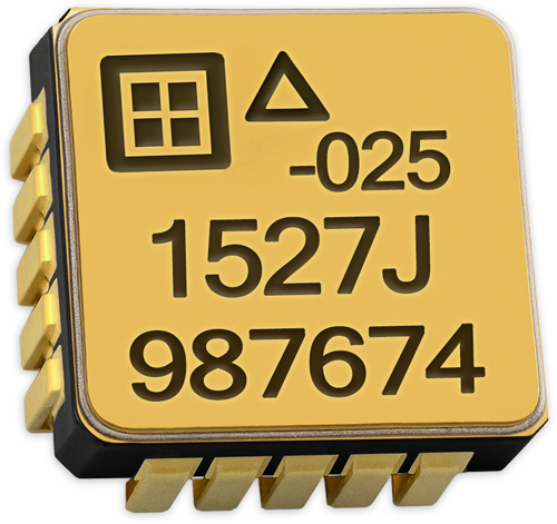
SDI 1527 TACTICAL-GRADE INERTIAL SURFACE MOUNT ACCELEROMETERS
The SDI Model 1527 delivers tight bias repeatability, exceptional thermal performance, and low-noise output in a compact, rugged surface-mount package.
Meet the SDI Model 1527: Precision Accuracy and Long-Term Reliability
The SDI Model 1527 is a tactical-grade MEMS DC accelerometer purpose-built to replace quartz accelerometers and incorporate a more durable design with lower mass and minimal power requirements. Fully developed and manufactured in the U.S., it combines a high-performance MEMS sense element with a ±4.0V differential output, integrated temperature sensor, and nitrogen-damped, hermetic surface-mount package.
Rated from -55°C to +125°C, this accelerometer excels in navigation, robotics, defense, and aerospace applications, and anywhere stability, low noise, and precision are required over extended periods.
Key Features And Use Cases
- Excellent In-Run Bias Stability
- Zero Cross Coupling by Design
- Allan Variance from 5 μg
- Available in ±10g, ±25g, and ±50g
- -55 to +125°C Operation
- ±4V Differential Output
- +5 VDC, 6.5 mA Power (Typical)
- Internal Temperature Sensor
- Nitrogen Damped & Hermetically Sealed
- Serialized for Traceability
- 9 mm sq. J-Lead LCC-20 Package
- Low Mass: 0.68 grams
- Inertial
- Navigation
- Instrumentation
- OEM Integration
- Robotics
Accuracy, Noise Reduction, and Operational Consistency
Designed for performance-critical applications, the 1527 balances mechanical ruggedness with electrical clarity and repeatable measurements across its entire thermal range.
Built for Accuracy in Harsh Conditions
With bias repeatability better than 2 mg and tight scale factor stability, the Model 1527 ensures your system receives reliable, high-accuracy measurements, even in dynamic environments. Its minimal rectification error and axis misalignment allow it to perform with consistent precision.
Low Noise for Clean, Reliable Data
With a low-noise MEMS architecture and integrated amplifier, the 1527 delivers clean, analog output across ±10g to ±50g ranges. This minimizes the need for external filtering and preserves signal quality in applications like vehicle stabilization, flight instrumentation, and navigation subsystems.
Compare Specifications
DESIGN SPECIFICATIONS
Unless otherwise specified VDD=VR=5.0 VDC, TC=25°C, Differential Output, J-lead package
| PARAMETER | TYPICAL VALUE/RANGE +/-10G |
TYPICAL VALUE/RANGE +/-25G |
TYPICAL VALUE/RANGE +/-50G |
UNITS |
|---|---|---|---|---|
| Vibration Rectification, typical: Random, 10-50 Hz |
20 | 35 | 50 | μg/g2 rms |
| Vibration Rectification, typical: Random, 50-200 Hz |
50 | 100 | 150 | μg/g2 rms |
| Velocity Random Walk | 0.007 | 0.012 | 0.025 | m/s√Hr½ |
| Bias, Long Term Repeatability (1σ) | 1.25 | 1.50 | 3.0 | mg |
| In Run Bias Stability at +1g, 2-40,000 sec. (AV Min | 12 | 30 | 60 | μg |
| Scale Factor Long Term Repeatability (1σ) | 300 | 300 | 300 | PPM |
| Output White Noise | 18 | 25 | 50 | μg/√Hz½ rms |
| Temperature Sensor Sensitivity (IT Pin 7) | 1.2 to 1.8 | 1.2 to 1.8 | 1.2 to 1.8 | uA/°C |
| Temperature Sensor Noise | 0.33 RMS typ | 0.33 RMS typ | 0.33 RMS typ | C |
| Turn-On Time < 150 ppm of FS | 0.5 | 0.5 | 0.5 | msec |
| Operating Voltage | 4.75 to 5.25 | 4.75 to 5.25 | 4.75 to 5.25 | Volts |
| Input Axis Misalignment, typical | 4 | 4 | 4 | mrad |
| Peak Vibration (Operating and Non-operating) | 200% | 200% | 200% | FS |
| Mass | 0.68 | 0.68 | 0.68 | grams |
MAX OPERATING LIMITS
| PARAMETER | MINIMUM | MAXIMUM | UNITS |
|---|---|---|---|
| Differential Output | -4.0 | +4.0 | Volts |
| Operating Voltage | 4.75 | 5.25 | Volts |
| Quiescent Operating Current at +5V | – | 6.5 | mA |
| Operating / Storage Temperature | -55 | +125 | ⁰C |
| Applied Voltage on Digital Pins | -0.5 | 5.5 | Volts |
| Mechanical Shock (0.1 ms) | – | 5000 | g-peak |
| Peak Vibration (Operating and Non-operating) | 200 | % of full scale |
NOTICE: Stresses greater than those listed may cause permanent damage to the device. These are maximum stress ratings only. Functional operation of the device at or above these conditions is not implied.
Each miniature, hermetically sealed package combines a MEMS capacitive sense element and a custom integrated circuit that includes a sense amplifier and differential output stage. It is relatively insensitive to temperature changes and gradients. Each device is individually tested, programmed, calibrated by SDI, as well as marked with a serial number on its top and bottom surfaces for traceability. A calibration test report (1527-TST) is provided with every unit showing the measured bias, scale factor, linearity, operating current, & frequency response.
Need Help Choosing the Right Accelerometer?
Performance and Packaging
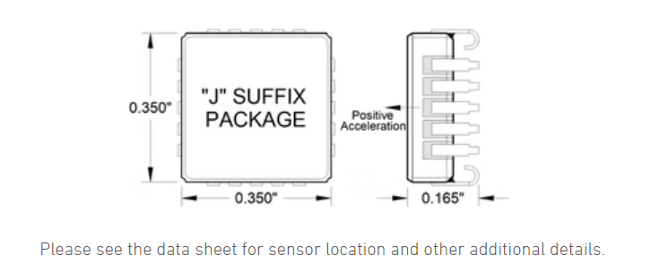
The Model 1527 is housed in a 9 mm square J-lead LCC-20 package that is hermetically sealed and nitrogen damped. It includes an internal temperature sensor and amplifier, and operates on +5 VDC at just 6.5 mA typical. Its compact form factor allows seamless integration into space-constrained, high-performance OEM designs.
Package Dimensions
TESTED PERFORMANCE SPECIFICATIONS
Scale = measured value; FS = Full Scale = absolute output = 4000 mV
| PARAMETER | MIN | TYP | MAX | UNITS |
|---|---|---|---|---|
| Bias | +/- 0.5 | +/- 0.5 | +/- 0.5 | ± % of full scale |
| Bias Temperature Coefficient | +/-25 | +/-15 | +/- 15 | PPM of FS/⁰C |
| Scale Factor Sensitivity, +/-0.5% | 400 | 160 | 80 | mV/g |
| Scale Factor Temperature Coefficient | +/-25 | +/-25 | +/-25 | PPM/ ⁰C |
| RMS Model Residual (+/- 1g, -40, +25, +85⁰C) | 30 | 25 | 25 | PPM of full scale |
| Frequency Response, DC to -3 dB, Minimum* | 420 | 660 | 1050 | Hz |
Operational Highlights
The model 1527 sensitive axis is perpendicular to the bottom of the package, with positive acceleration resulting from a positive force pushing on the bottom of the package. The seismic center is located on a centerline through the dual sense elements and halfway between them.
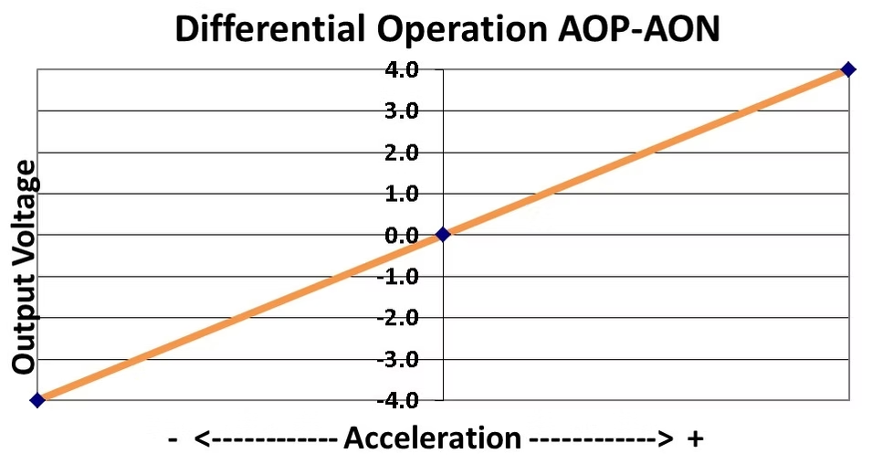
The Model 1527 produces a differential +/-4 volts output voltage, the value of which varies with acceleration as shown in figure 1. Any errors due to rotation about this point are effectively cancelled by the internal electronics.
Two reference voltages, +5.0 and +2.5 volts (nominal), are required; scale factor is ratiometric to the +5.0 volt reference voltage relative to GND, and both outputs at zero acceleration are nominally 80 mV below the +2.5 volt input.
Sales and Support
Reliable Customer Support from Start to Finish
Get a Quote
Our sales team is available to assist with pricing, lead times, and customized solutions tailored to your specific needs. We work closely with you to ensure you get the best accelerometer solution for your application.
Order Now
With a streamlined ordering process and secure procurement options, placing an order with SDI is simple and efficient. Our commitment to fast processing ensures minimal downtime for your projects.
Tech Support
From initial setup to ongoing performance optimization, our technical support team provides expert guidance to ensure proper integration and reliable sensor operation.
Our Distributors
Our experienced U.S. sales representatives provide direct assistance for domestic customers, ensuring a smooth procurement process with personalized service. International customers can rely on our global distributor network for localized support, timely deliveries, and expert guidance in their regions.
Sign Up For Our Newsletter
Sign up for our newsletter to receive the latest insights on sensor technology, industry trends, and product updates. Be the first to know about advancements in MEMS accelerometers and how they can benefit your applications.