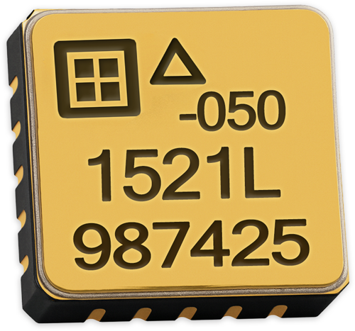
SDI 1521 SURFACE MOUNT ACCELEROMETERS
Low noise and long-term stability in a rugged, surface mount MEMS accelerometer.
Meet the SDI 1521: A Go-To Accelerometer for Stable, Low-Noise Performance
The SDI Model 1521 Industrial-Grade Surface Mount Accelerometer offers exceptional ruggedness and precision in a compact footprint. Ideal for zero-to-medium frequency commercial and industrial applications, it supports ±2g to ±400g ranges and is available in both leadless LCC and J-Lead packages. Whether you’re designing for automotive, robotics, seismic, or instrumentation systems, the 1521 ensures dependable sensing with unmatched durability.
Key Performance Features
- Low Noise: 7 μg/√Hz Typical for ±2g Full Scale Versions
- Responds to frequencies from zero (DC) to 4000+ Hz
- High Stability and Durability
- -55 to +125°C Operation
- ±4V Differential Output
- +5 VDC, 5 mA Power
- Integrated Sensor & Amplifier
- Internal Temperature Sensor
- Nitrogen Damped & Hermetically Sealed
- Serialized for Traceability
- RoHS Compliant
Why Choose SDI’s 1521 Surface Mount Accelerometer
Reliability, Low Noise, and Durability in Every Detail
The Model 1521 offers proven reliability, ultra-low noise, and lasting durability, making it a trusted solution for engineers who need dependable data in high-demand environments.
Proven Durability for Demanding Environments
The 1521 is built to perform reliably in rugged industrial and OEM settings. Its nitrogen-damped, hermetically sealed casing protects sensitive internal components, while integrated amplification and differential output ensure consistent, high-quality signal performance under mechanical and environmental stress.
Exceptionally Low Noise for Clean, Accurate Signal Output
With noise levels as low as 7 μg/√Hz in the ±2g version, the Model 1521 excels in applications where details matter. This low noise MEMS accelerometer is particularly well-suited for vibration detection, instrumentation, and motion tracking systems that rely on high-fidelity output.
Compare Specifications
| g Range | Sensitivity, Differential |
Frequency Response (Typ, 3 dB) |
Frequency Response (Min, 3 dB) |
Frequency Response (Typ, 5%) |
Output Noise, Differential (RMS, Typ) |
Max. Mechanical Shock (0.1 ms) |
|---|---|---|---|---|---|---|
| g | mV/g | Hz | Hz | Hz | μg/(root Hz) | g (peak) |
| ±2 | 2000 | 0 – 525 | 0 – 300 | 0 – 250 | 7 | 2000 |
| ±5 | 800 | 0 – 800 | 0 – 420 | 0 – 400 | 12 | 2000 |
| ±10 | 400 | 0 – 1100 | 0 – 660 | 0 – 700 | 18 | 5000 |
| ±25 | 160 | 0 – 1750 | 0 – 1050 | 0 – 1300 | 25 | 5000 |
| ±50 | 80 | 0 – 2100 | 0 – 1400 | 0 – 1600 | 50 | 5000 |
| ±100 | 40 | 0 – 3000 | 0 – 1700 | 0 – 1700 | 100 | 5000 |
| ±200 | 20 | 0 – 3600 | 0 – 2100 | 0 – 1900 | 200 | 5000 |
| ±400 | 10 | 0 – 4200 | 0 – 2400 | 0 – 2000 | 400 | 5000 |
SDI’s compact, hermetically sealed package integrates a MEMS capacitive sense element for DC measurement with a custom IC that includes a precision sense amplifier and differential output stage. This configuration minimizes sensitivity to temperature shifts and gradients, ensuring consistent performance across a wide thermal range. Every unit is individually tested, programmed, and calibrated by SDI, then serialized on both the top and bottom surfaces for full traceability. For added validation, an optional calibration test report (1521-TST) is available, detailing each accelerometer’s measured bias, scale factor, linearity, operating current, and frequency response.
Need Help Choosing the Right Accelerometer?
Performance and Package Options
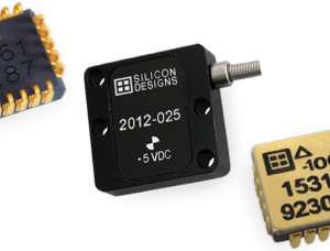
This small accelerometer is designed with both compactness and performance in mind. Choose from leadless or J-lead formats to match your design requirements without sacrificing output quality or long-term reliability.
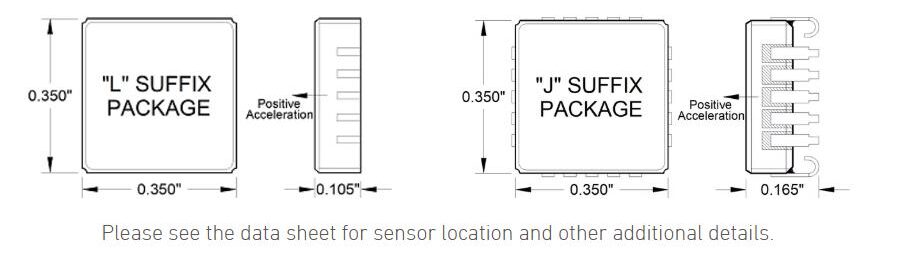
Package Dimensions
Performance – All Versions
All Models: Unless otherwise specified VDD=VR=5.0 VDC, Tc=25°C, Differential. Span = ±g range = 8000 mV
| PARAMETER | MIN | TYP | MAX | UNITS |
|---|---|---|---|---|
| Bias Calibration Error (mV) | 16 | 40 | ± mV | |
| Bias Calibration Error (Span) | 0.2 | 0.5 | ± % of span | |
| Bias Temperature Shift (Tc= -55 to +125°C) 1 | -200 | 0 | +200 | (PPM of span)/°C |
| Scale Factor Calibration Error 2 | 0.5 | 1 | ± % | |
| Scale Factor Temperature Shift (Tc= -55 to +125°C) 1 | -200 | 0 | +200 | PPM/°C |
| Non-Linearity (-90 to +90% of Full Scale) 1,2 | 0.15 | 0.5 | ± % of span | |
| Long Term Bias Stability | 1000 | 2000 | ± PPM of span | |
| Long Term Scale Factor Stability | 500 | 1000 | ± PPM | |
| Cross Axis Sensitivity | 2 | 3 | ± % | |
| Input Axis Misalignment | 5 | 10 | ± mrad | |
| Turn-On Transient (in less than 0.5ms) | 75 | ± PPM of FS | ||
| Output Impedance | 90 | Ohms | ||
| Operating Voltage 3 | 4.75 | 5.0 | 5.25 | volts |
| Operating Current (IDD+IVR) | 5.5 | 6.5 | mA | |
| Mass: 'L' package (add 0.06 grams for 'J' package) | 0.62 | grams | ||
| Case Operating Temperature | -55 | +125 | degrees C | |
| Storage Temperature | -55 | +125 | degrees C | |
| Max Reflow Solder Temperature | +239 | degrees C |
Note 1: Tighter tolerances are available on other SDI accelerometers.
Note 2: For 2g thru 50g only; 100g and greater versions are tested and specified from -65 to +65g.
Note 3: Voltages on pins other than DV, GND or VDD may exceed 0.50 volt above or below the supply voltages provided the current is limited to 1 mA.
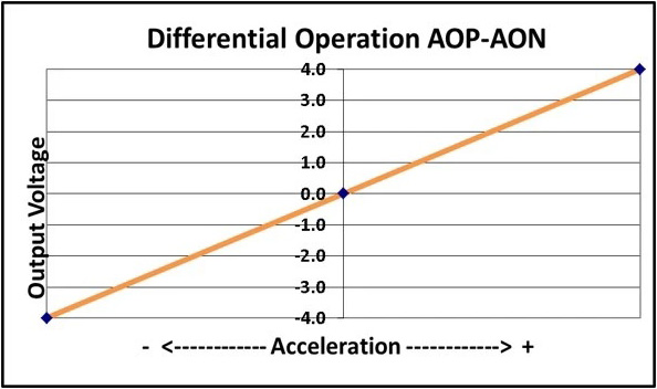
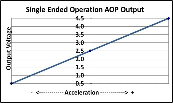
Operational Highlights
The Model 1521 produces a differential +/-4 volts output voltage or single ended mode, 0.5 – 4.5 volts full scale, the value of which varies with acceleration as shown in the figures below. The sensitive axis is perpendicular to the bottom of the package, with positive acceleration resulting from a positive force pushing on the bottom of the package. The seismic center is located on a centerline through the dual sense elements and halfway between them. The internal electronics effectively cancel any errors due to rotation.
Two reference voltages, +5.0 and +2.5 volts (nominal), are required; scale factor is ratiometric to the +5.0 volt reference voltage relative to GND, and both outputs at zero acceleration are the same as the +2.5 volt input.
Frequently Asked Questions
Why does the accelerometer read zero G's when it's in free fall?
All accelerometers are used to measure increasing or decreasing acceleration, and they can detect vibration because it is a change in acceleration between multiple directions. Free fall, by definition, is a static acceleration, which means the object may be moving, but its acceleration is not changing at all. SDI’s MEMS DC accelerometer technology allows it to measure free fall because it doesn’t require any change of acceleration to supply data, and therefore it will report back 0g of acceleration.
How do I choose the right g-range for my application?
The g-range of your accelerometer should match the maximum acceleration your system is expected to experience—but avoid going unnecessarily high. Selecting too high of a g-range can reduce measurement clarity, while too low of a range can cause the sensor to saturate if the acceleration exceeds its limit. Also consider the frequency response. Each Silicon Designs sensor has a MEMS sense element tuned to its specific g-range, which affects its frequency range and noise profile. Be sure to check the product datasheet or visit our How To Choose Your Accelerometer guide for more detailed recommendations. You can also reach out to our team for help identifying the best fit for your application.
Optional Accessories
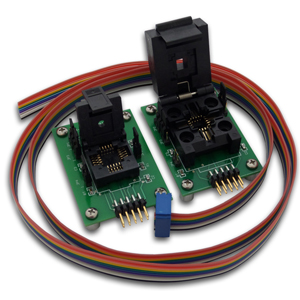
MODELS EB-L & EB-J ANALOG TEST SETS
- INFO
- STATS
- Compatible Sensor Models: 1521 I 1522 I 1525 I 1527 I 1531
- Socket Types: JLCC or LCC
-
Includes:
- Test board
- ZIF socket
- 10-pin ribbon cable
- jumpers
- Use with: SDI 3340 G-Logger DAQ
Need Enhanced Temperature Performance?
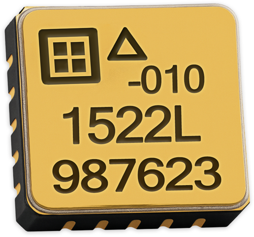
SDI 1522 SURFACE MOUNT ACCELEROMETERS
- INFO
- STATS
- APPLICATIONS
- Power: +5 VDC
-
Output:
- Differential: +/- 4 V
- Single Ended: +0.5V to +4.5V
- Current: 5 mA
- Mass: LCC: 0.62 grams
-
Package:
- J-Lead 20 Pin LCC
- Material: Gold & Ceramic
- Size: 9mm x 9mm x 5mm
- Temperature: -55 to +125°C
- Elevator monitoring
- Platform leveling
- Flight test systems
- Hostile environment R&D
- Calibrating other accelerometers
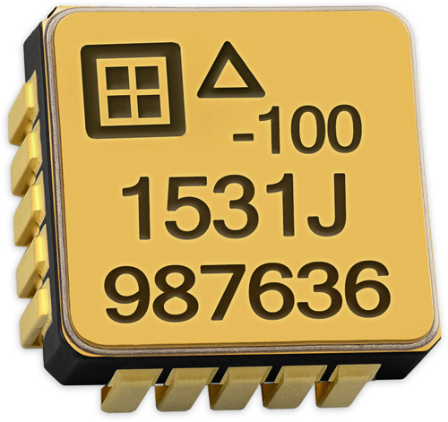
MODEL 1531 HIGH-TEMPERATURE TO +175°C
- INFO
- STATS
- APPLICATIONS
- Power: +5 VDC
-
Output:
- Differential: +/- 4 V
- Single Ended: +0.5V to +4.5V
- Current: 5 mA
- Mass: J-LCC: 0.68 grams
-
Package:
- J-Lead 20 Pin LCC
- Material: Gold & Ceramic
- Size: 9mm x 9mm x 5mm
- Temperature: -55 to +175°C
- Drillstring vibration monitoring
- Wellbore surveying
- Directional navigation
- Formation measurement
- Downhole equipment shock information
Sales and Support
Reliable Customer Support from Start to Finish
Get a Quote
Our sales team is available to assist with pricing, lead times, and customized solutions tailored to your specific needs. We work closely with you to ensure you get the best accelerometer solution for your application.
Order Now
With a streamlined ordering process and secure procurement options, placing an order with SDI is simple and efficient. Our commitment to fast processing ensures minimal downtime for your projects.
Tech Support
From initial setup to ongoing performance optimization, our technical support team provides expert guidance to ensure proper integration and reliable sensor operation.
Our Distributors
Our experienced U.S. sales representatives provide direct assistance for domestic customers, ensuring a smooth procurement process with personalized service. International customers can rely on our global distributor network for localized support, timely deliveries, and expert guidance in their regions.
Sign Up For Our Newsletter
Sign up for our newsletter to receive the latest insights on sensor technology, industry trends, and product updates. Be the first to know about advancements in MEMS accelerometers and how they can benefit your applications.