Search
 Product Finder
Key Takeaways:
- Start with the measurement. DC response, noise, bandwidth, acceleration range, and temperature behavior all matter. No single specification determines whether an accelerometer is right for the application.
- Keep measurement range and survivability separate. Launch vibration and shock may exceed the range used for normal measurement, so both operating performance and mechanical survival limits need to be considered.
- Look at the whole signal path. Differential analog outputs can improve common-mode noise rejection, but cabling, grounding, shielding, receiver design, filtering, and data acquisition still affect the result.
- Plan for the life of the program. Product continuity, revision control, lead times, and technical support can become qualification issues when a program spans multiple vehicles or production years.
- Then test it. Datasheets narrow the field; bench and environmental testing show how the accelerometer behaves with the actual mounting, electronics, cabling, and acquisition system.
An accelerometer on a small satellite may see one set of conditions during launch and a very different set once the spacecraft is in orbit. Rather than asking whether a sensor is broadly “suitable for space,” it is more useful to ask whether its documented performance matches the acceleration levels, frequency content, temperature range, mechanical environment, and signal-chain requirements of the application.
That evaluation starts with the datasheet. It should end with the sensor installed in a representative mechanical and electrical setup and tested against the requirements that matter.
Criteria 1: Low-Frequency Response, Noise, and Bandwidth
Capacitive MEMS accelerometers provide continuous response down to 0 Hz DC, which is useful when the measurement includes static or very low-frequency acceleration as well as dynamic vibration. In a small satellite program, that can include low-frequency vehicle motion, propulsion-related acceleration, structural disturbances, and other events an AC-coupled sensor would not capture.
DC response is only one part of the picture. The expected acceleration spectrum and the smallest signal of interest need to be compared with the sensor’s performance across several specifications:
- DC response
- Noise density
- Bandwidth and frequency response
- Full-scale acceleration range
- Sensitivity
- Bias and sensitivity behavior over temperature
Those specifications work together. A low-noise sensor can still be the wrong choice if it lacks the required range or bandwidth; a device with ample range may not have enough resolution for low-level measurements.
Criteria 2: Measurement Range, Launch Vibration, and Shock Survivability
Launch can expose a sensor to vibration and transient shock well above normal on-orbit measurement levels. That makes it important to distinguish between two specifications that are sometimes treated as though they mean the same thing:
Measurement range is the acceleration that can be measured within the specified output range.
Shock survivability describes the mechanical shock level the device can withstand without damage.
A device may survive an event that exceeds its measurement range without producing useful in-range data during the event. The reverse is also true: a large measurement range does not establish shock survivability. For launch applications, compare the expected environment with the manufacturer’s published operating, over-range, vibration, and shock specifications, then decide what additional qualification testing the program requires.
Criteria 3: Temperature Performance and Packaging
Temperature affects accelerometer bias and sensitivity, so thermal performance is best judged from the relevant specifications and test data. Hermetic packaging protects the MEMS sensing element from contamination and environmental exposure, but it does not make the output independent of temperature.
For programs that include wide temperature excursions or thermal-vacuum testing, the useful numbers include:
- Operating temperature range
- Bias temperature coefficient
- Sensitivity temperature coefficient
- Repeatability and calibration behavior
- Any application-specific thermal characterization available from the manufacturer
For demanding programs, measured performance across the expected temperature range is more meaningful than a general claim of “thermal stability.”
Criteria 4: Telemetry Signal Integrity and EMI/RFI Susceptibility
Low-level analog measurements can pick up electrical noise from transmitters, power electronics, motors, reaction wheels, solar-array drives, and other onboard systems. Differential analog outputs can improve rejection of common-mode interference when they are paired with an appropriate differential receiver and a well-designed signal path.
That does not make the system immune to EMI or RFI. Signal integrity still depends on choices elsewhere in the design, including:
- Receiver architecture
- Cable routing
- Grounding and shielding
- Power-supply quality
- Filtering
- Analog-to-digital conversion and acquisition settings
For high-resolution measurements, the accelerometer and acquisition electronics are better evaluated as one signal chain than as isolated components.
Criteria 5: Program Lifecycle and Product Continuity
Small satellite programs often extend across multiple spacecraft, production lots, and deployment years. If a qualified accelerometer is discontinued or materially changed, the resulting redesign and requalification effort can matter far more than the price of the component.
It is worth asking about the supplier as well as the sensor:
- Expected product availability
- Revision-control practices
- Manufacturing continuity
- Lead-time consistency
- Form, fit, and function stability
- Availability of applications and technical support
The goal is not simply to find a part that works in the first build. It is to select a device that can remain practical and supportable for the duration of the program.
A Practical Small Satellite Accelerometer Checklist
Before committing to a device, ask the manufacturer the following questions and look for the answers in datasheets, test data, or other documented performance information:
- Does the accelerometer provide true DC response?
- What is the noise density in the frequency range of interest?
- Which acceleration ranges are available?
- What are the published vibration, over-range, and shock-survival limits?
- How do bias and sensitivity change with temperature?
- What output architecture does the device use?
- What interface and signal-conditioning practices are recommended?
- What characterization or qualification data are available?
- How consistently is the product configuration controlled across production lots?
- What is the manufacturer’s history and policy for long-term product support?
Those answers are usually more useful than broad labels such as “space-capable,” “high stability,” or “high shock.”
Meeting Space Demands with Silicon Designs MEMS DC Accelerometers
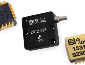
Silicon Designs manufactures capacitive MEMS DC accelerometers using a differential variable-capacitance sensing architecture. SDI accelerometers provide continuous response down to 0 Hz DC and are available in multiple acceleration ranges for applications that need both low-frequency and dynamic acceleration measurement.
Many SDI accelerometers also provide differential analog outputs, giving system designers the option of differential signal acquisition where common-mode noise rejection is important. Silicon Designs manufactures its accelerometers entirely in the United States and has maintained long production lifecycles for its product families.
For small satellite and aerospace applications, the selection still comes back to the requirements. Noise, bandwidth, acceleration range, shock survivability, temperature performance, package configuration, and output type all have to fit the job. The strongest evidence is documented performance that matches the application, followed by successful testing in the intended system.
Prove Accelerometer Performance in the Intended System
Datasheets tell you whether a part belongs on the short list. Testing tells you whether it belongs in the design.
Whenever possible, evaluate candidate accelerometers with the same acquisition electronics, cabling, mounting approach, filtering, and environmental conditions expected in the application. This is where system-level effects become visible: noise pickup, grounding sensitivity, usable dynamic range, mounting effects, and signal behavior during real mechanical events.
Silicon Designs works directly with engineering teams evaluating MEMS accelerometers for aerospace and small satellite applications. Request a sample for evaluation, or contact SDI to discuss the acceleration range, bandwidth, noise, temperature performance, and mechanical requirements of your application.
Frequently Asked Questions About MEMS Accelerometers for Small Satellites
What is the advantage of a MEMS DC accelerometer in a small satellite application?
A capacitive MEMS DC accelerometer can measure acceleration continuously down to 0 Hz, so the same sensor can capture very low-frequency or steady acceleration as well as dynamic motion within its bandwidth. Whether that matters in a particular design depends on the measurement requirement, noise floor, range, and signal chain.
Does shock survivability mean the accelerometer can measure the full launch shock event?
No. Shock survivability and measurement range describe different things. A device may survive an acceleration that exceeds its usable measurement range, so both the required measurement range and the published mechanical shock limits need to be reviewed.
How should temperature performance be evaluated?
Start with the operating temperature range and the published changes in bias and sensitivity with temperature. If the thermal requirements are demanding, test the accelerometer across the expected temperature range using the intended electronics and mounting configuration.
Do differential outputs eliminate EMI problems?
No. Differential outputs can improve rejection of common-mode electrical interference, but EMI/RFI performance depends on the entire signal path: receiver, cabling, grounding, shielding, power, filtering, and data-acquisition design.
Why does long-term component availability matter for a small satellite program?
If a program spans multiple vehicles or production years, a discontinued or materially changed component can force hardware requalification. Product continuity, revision control, and supplier support therefore belong in the initial component-selection discussion.